What is CAM (Computer Aided Machining) Software?
CAM Software is the software that takes your CAD (Computer Aided Design) drawing or artwork that you want to cut and gets it ready for the machine. CAM (Computer Aided Machining) is where you’re going to set up the cut by telling the machine what you’re cutting (Aluminum, Steel, Stainless Steel etc.). It also tells the machine how thick the material is, sets up your lead ins and outs, cutting amps, cut speed, and a host of other data. Most of the settings and operations will be automated to some degree. Most of the values will have been set up previously, or settings can be imported to match your plasma cutter.
Hypertherm does an excellent job of testing and evaluating materials and machine settings to perfect them. They have all the specifications and settings information for nearly every material that you would ever cut. Their settings are based on ideal circumstances, with brand new consumables. The capabilities and design of your plasma table, as well as the material that you use, can vary slightly. A little tweaking to the settings may be necessary for your application, but the cut charts from Hypertherm are a great place to start and have all the info that you need.
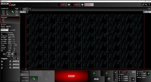
Many of the higher end and industrial plasma tables come with a proprietary CAM software, like our Design2Cut software. Unlike the artwork software, the CAM software must be programmed to specifically match up to the plasma table, control system, and plasma cutter.
Pierces and Lead-Ins
When the plasma torch fires and punches through the material (piercing) it’s going to make a bigger hole than the following cut line. This pierce hole is undesirable to have in your finished project, so you use lead-ins. These are small lines that connects to your part. The torch pierces at the start of this small line segment so that the finished part does not have pierce in it. The pierce takes place in a waste area of the cut. Typically, the higher the amperage and thicker the material, the larger the pierce hole will be. Thus, the lead-in will be larger for thicker vs. thin material.
Kerf
Another component of the CAM software is knowing kerf. Kerf is the width of the cut. This is the thickness of the plasma. Lower amperage / thinner materials will have smaller kerf than thicker material with high cut amperage.
The CAM program automatically places the lead-ins and outs and adjusts the cut line based on the estimated kerf of the cut. All the start points are numbered.
A deeper explanation of CAM (Computer Aided Machining) Software
The CAM program is going to take all of the settings you have picked for your material, the thickness, as well as all of the information from your drawing then turn that into something the machine can use to complete the task. There are literally hundreds of variables that CAM program will control. Each of these vary from program to program, but most will automate this very complex process into something very simple that can be done with just a few clicks. The CAM program usually will create some form of G-Code to accomplish this.
G-Code is the language the machine speaks. The reason CAM software and the G-Code that it generates cannot be moved from machine to machine is because these software components have specific information that is unique to your machine and its setup. Trading G-Code files is not recommended. The results are most likely not going to work. Instead, you can trade or use other peoples .dxf files. Then process them in your CAM software and export them to your machine. There are many sites available on the Internet where you can get or purchase artwork ready to go.
Unique info can include the size and configuration of your steppers or servos, machine table size, plasma cutter and its settings, design of your table, Z axis setup, accessories like air scribes, or rotary devices. Ultimately check with your plasma table manufacturer and the CAM software manufacturer to ensure compatibility with your system.
What do we recommend / use?
For our Titan Series X and Pro Series plasma table, we are using Design2Cut for our CAD, CAM, and CUT program. While this program is proprietary to Westcott Plasma, it can be adapted and used with other brands, or retrofitted to machines using other software options. What is unique with Design2Cut is that it is an all in one solution for your software. Meaning that it can take the place of three programs and allow you to build a CAD part, Complete CAM processing, and send it to the Machine for cutting all in one program. This greatly simplifies the task of making something.
You can still use other CAD design programs and import the drawings into Design2Cut. Some people may be comfortable with other design software, so you’re not limited in that regard with Design2Cut.
To instantly access a free demo of Design2Cut, check out our resources page.
We will be doing tutorial videos on our Westcott Plasma YouTube, Westcott University, and we will also have some tips & tricks on our Westcott Plasma blog.