
Achieving the best possible cut quality is always the goal, understanding what factors contribute and being able to identify and correct the problems is the skill you need to master. For specific information on consumables check the consumables tips and tricks page.
What factors contribute to cut quality?
- Air Quality – Having clean, dry, oil free air is a must. It affects cut quality and consumable life.
- Torch Height – Both for pierce and cut, ensuring that the machine maintains the correct height at all times is critical.
- Cut Direction – Ya that’s a thing. The squarest cut angles are always on the right side, with respect to the torch and its movement. On an outside cut the torch, should move clockwise and on inside cuts (holes) it should move counter clockwise.
- Consumables – Making sure your consumables and torch components are clean and within spec. Nozzle hole is round and not out of round and no debris is on the nozzle or swirl ring.
- Torch Square – Ensuring that the torch itself is perfectly square to the work surface will decrease the chance of having bevel on your cuts.
- Proper cutting speed – Making sure that you are following the proper specs and that your machine is accurately carrying out that move. Doing tests with a stop watch and tape measure can ensure that your machine is actually moving at the speed it says it is.
- Vibration – Even if your torch is perfect, you can still have problems is there is vibration, or play, in your machine. This will affect cut quality, especially at higher speeds and detailed work with quick motion changes.
- Out of Square – If your gantry or machine is not square your resulting parts will not be square.
Lets Talk Bevel
Typical bevel for air plasma is 1 to 3 degrees, this is normal and accepted for the process. Here are some pictures of bevel problems and what causes them.
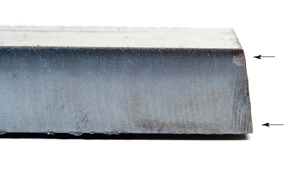
Positive bevel (top of part, smaller than bottom)
This problem may be caused by a worn nozzle, high torch standoff (arc voltage), inadequate amperage, or excessive speed. All of these variables cause the arc to lag which causes more energy to contact the top of the kerf than the bottom. As a result, the kerf is wide at the top and narrow at the bottom. Improper cut direction around the part may also cause excessive positive bevel angle. A part with excessive positive bevel all around it may also have a hard bead of high-speed dross at its bottom edge.
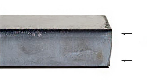
Negative bevel (bottom of part, smaller than top, undercutting)
This problem can be caused by low torch standoff (arc voltage), excessive amperage, or low speed. These parameters cause the arc to remove more material at the bottom of the plate. Usually a consistent negative bevel around the part is accompanied by low speed dross.
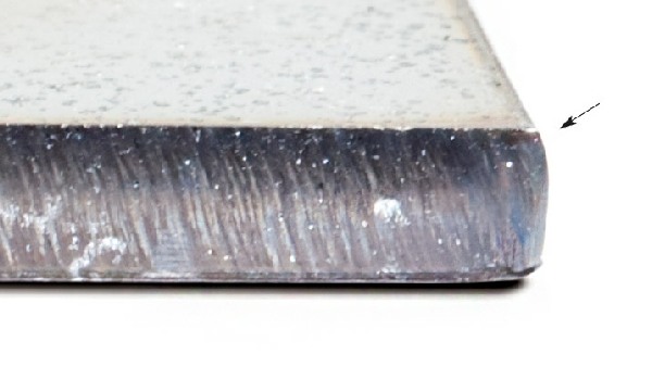
Irregular bevel (concave and convex cut, surface shown on a cut away)
Positive cut surface – positive and negative bevel on the same piece.
This problem usually indicates that the nozzle has failed, the torch is out of square, or the electrode and nozzle are misaligned. These variables cause the arc to deviate from a straight path through the material. Often, one side of a square part will have a positive bevel and the opposing side a negative. The cross section of the part looks like a parallelogram, rather than a rectangle. Sometimes the cut surface may not be flat, but rather concave on one side and convex on the other.
These are all signs of severely worn or misaligned parts.
Dross
That left over metal on the edges of our cuts. Perfect dross free cuts every time is not a reality. You can get close if everything is dialed in correctly.
High speed dross
The cutting speed is too fast. This type of dross is harder to remove. Sometimes you can see the torch leaving a rooster tail as it cuts. You may fail to fully penetrate the material. High standoff, or low amperage, for the material being cut can also cause this.
Corrections
- Check the nozzle first for signs of wear (gouging, oversize, or elliptical orifice)
- Decrease the cutting speed in 5 ipm increments
- Decrease the standoff in 1/16 increments or 5 volts increments
- Increase the amperage (but do not exceed 95% of the nozzle orifice rating)
Low speed dross
Cutting speed is too slow. You will be begin to widen your kerf as the plasma jet tries to consume more material than you want. Excessive amperage or low standoff can also cause low-speed dross. (Some low speed dross in the corners of a plasma cut is normal since velocity does not remain constant through a sharp turn).
Corrections
- Increase the cut speed in 5 ipm increments
- Increase the standoff in 1/16 increments or 5 volt increments
- Decrease the amperage in 10 amp increments
- If none of these measures improve the cut, consider a smaller nozzle size
Top spatter dross
Top spatter is an accumulation of re-solidified metal that sprays along the top of the cut piece. It is usually very easy to remove. A worn nozzle, excessive cutting speed, or a high standoff is usually the cause. It is caused by the swirling flow of the plasma jet which, at a certain angle of attack, flings molten material out in front of the kerf rather than down through it.
Corrections
- Check the nozzle for signs of wear
- Decrease the cutting speed in 5 ipm increments
- Decrease the standoff in 1/16 increments or 5 volt increments
Other factors
The cleaner steel and cold rolled steel will typically have less dross than dirty or hot rolled steel.
To achieve cuts with the least amount of dross, you can do a series of straight line cuts at different speeds and select the speed that gives you the best results for your material. Even when conditions are perfect, it’s still normal to end up with dross in the corners and in detail work because the torch will be forced to slow down and thus be out of the dross free window.
Piercing
Pierce high and cut low: The rule of thumb is to pierce at 1.5-2X the cut height or at the maximum transfer distance. Piercing high prevents double arcing, bridging, and snuffing.
Use a creeping pierce: If your CNC is capable, use a creeping pierce. This feature slowly moves the torch during the pierce operation causing the “rooster tail” of molten material to miss the front end of the torch. (Think of the shot glass with the water streaming into one side rather than the middle).
Don’t eyeball the pierce height: Use the initial height sensing if it is available. Manual piercing is usually not recommended. Even experienced operators don’t have a perfectly calibrated eye.
Don’t pierce beyond system limits: Pierce rating is typically 1/2 the cut rating.
Avoid piercing: Whenever possible use chain cutting or edge starting (for example off the edge of a punched hole) to reduce the number of pierces.
Cut height
Proper cut height is critical due to the shape of the plasma arc. The arc is an hour glass type shape and if your height is not correct you will end up with excessive bevel. Either top bevel or bottom bevel.
The 10 most common plasma cutting mistakes
A combination of fast cut speeds and low operating cost make plasma cutting one of the most productive metal cutting processes around. But there’s an “if.” You need to have a good operator and you need to keep your plasma system and table (if you’re using a table-based system) in good shape, as discussed in previous posts outlining daily, weekly, and monthly preventive maintenance tasks.
Another thing that really helps system performance and consumable life: avoiding common plasma cutting mistakes. Here’s our list of the top 10 things to avoid.
- Using consumables until they “blow”
- Changing consumables too often
- Using the wrong parameters & parts for the job
- Assembling the torch incorrectly
- Neglecting routine maintenance
- Not checking gas and coolant flow
- Piercing too low
- Cutting too fast or too slow
- “Stretching” the arc
- Crashing the torch

